
"Fluidistor" Gas Flow MeterGD 300 Ex / GD 500 Ex
"Fluidistor" Gas Flow MeterGD 300 Ex / GD 500 Ex
Our experience - your success!
Welcome to “Fluidistor”!!
The Fluidistor gas flow meter offers a solution for precise gas quantity measurement that is crucial for your success.
As manufacturer of the Fluidistor, Esters Elektronik GmbH can draw on nearly 50 years of experience in the industrial area of measurement and control technology.
The Fluidistor gas flow meter GD 300 Ex / GD 500 Ex is developed and produced exclusively in Germany by qualified specialists.
See for yourself!
Basic questions about the Fluidistor!

What is a Fluidistor?
A “Fluidistor” is a gas flow meter for gas quantity or gas volume measurements.
The type designations are GD 300 Ex or GD 500 Ex.
What is the Fluidistor measurement principle?
The Fluidistor flow meter GD 300 Ex / GD 500 Ex operates according to the principle of a „Fluidistor oscillator“.
The gas passes the Fluidistor measuring head either directly or via an orifice in the main pipe.
What kind of gases can be measured?
The Fluidistor can be used to measure biogas, industrial gases as well as all technical and medical gases.
Wet and dirty gases?
No problem!
The measuring of wet and dirty gases, such as sewage gas, biogas or contaminated industrial process gases do not influence the measurement results.
Mixed gases with a variable gas composition/mixtures?
No problem!
Changes of the gas composition in mixed gases do not affect the measurement result.
Maintenance! Expensive?
No!
The Fluidistor keeps you independent!
The replacement of the platinum wire sensor or a cleaning of the Fluidistor can be done by yourself on site.
No recalibration required!
Application Areas
Sewage gas
The Fluidistor is the functioning alternative!
Biogas
The Fluidistor is the functioning alternative!
Medical gases
Industrial gases
The Fluidistor also works with changing gas mixtures!
Compressed air controlling
Hydrogen
Examples of Application
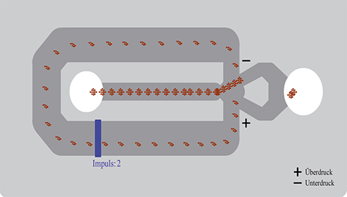
Principle of Measurement
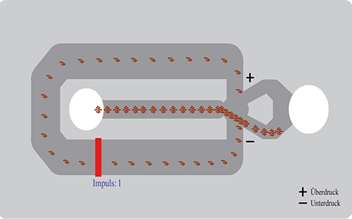
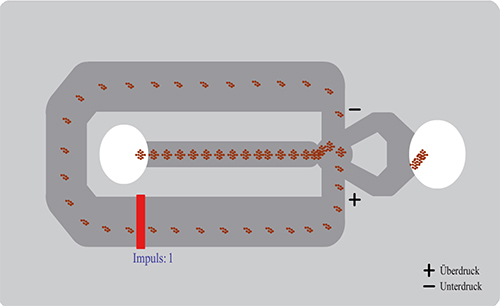
The Fluidistor gas flow meter GD 300 Ex/GD 500 Ex operates according to the principle of a „Fluidistor oscillator“. The gas passes the Fluidistor measuring head either directly (GD 500 Ex) or via an orifice (GD 300 Ex) in the main pipe.
The gas is discharged through the orifice into the
Fluidistor measuring chamber. Directly behind the inlet there is a triangular damming body, which, due to the unstable middle position, forces the gas either to flow past on the right or left. At the level of the damming body …
A detailed description can be found either in our video or click “More”!
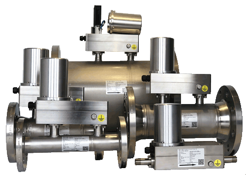
Overview and Highlights
The Fluidistor gas flow meter GD 300 Ex / GD 500 Ex is used for gas volume measurements and for technical and medical gases.
The flow meters work on the principle of “fluidistor oscillator”. The measuring principle is dense independent and has no moving parts, thus there are no wearing parts in place and a recalibration is not necessary.
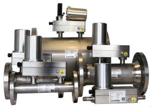
The Fluidistor gas flow meters are available from DN 15 – DN 400.
- DN 15 – DN 25 (1/2″ – 1″) with an external pipe thread
- DN 25 – DN 400 sandwich / Wafer
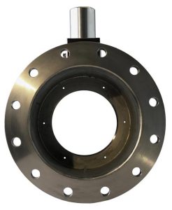
- DN 40 – DN 400 with flange
Highlights
- oscillating measuring principle suitable for almost all types of gas (including mixed gases), no moving components
- oscillating measuring principle suitable for almost all types of gas (including mixed gases), no moving components
- measuring housing, orifice and measuring
labyrinth made of stainless steel, also available as heavy duty construction - resistant to dirt, e.g. oil, rust, sulphur
- excellent results measuring moist gases with condensate
- mounting in falling direction into gas lines even for 100 % wet biogas due to integrated condensate drain
- no influence on the measurement results with dirty, moist gases, e.g. sewage gas, biogas or contaminated industrial process gases
- no influence on the measurement results for mixed gases with variable gas compositions
- optional integrated ball valve (blocking valve) in the GD 300 for removal/installation of the platinum sensor without emptying the system
- integrated calculator HB 300 in the measuring head with mA- (normalization optional) or pulse output
- short response time T90 ≤ 50 ms
with a flow velocity ≥ 0,25 m/s - high accuracy (±1,5 % of true value)
- high reproducibility (0,1 % of true value)
- low pressure loss
- each flowmeter with calibration report
- no recalibration required
- Ex II 1 / 2 G Ex ia / e mb IIC T4 Ga / Gb (Zertifikat Nr. EX5 13 07 14689 003)
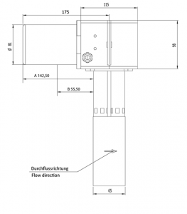
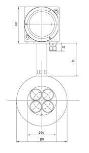
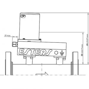
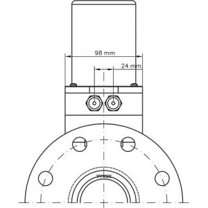
Technical Data
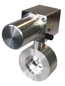
Nominal size:
DN 25 to DN 400
Process connection:
Wafer / Sandwich / intermediate flange
Installation lenght:
65 mm
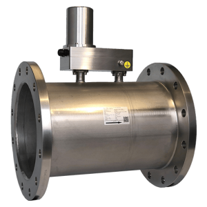
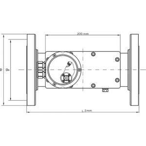
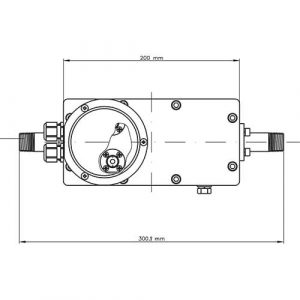
Nominal size:
DN 40 to DN 400
Process connection:
flange acc. to EN 1092-1 or
DIN 2576, flange acc. to ASME B 16.5
Installation lenght:
depending on nominal size (300 – 500 mm)
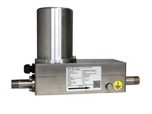
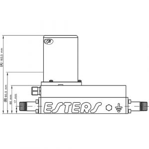
Nominal size:
DN 15, DN 25
Process connection:
external pipe thread
R 1/2”
G 1”
Installation lenght: 300 mm
With us you stay independent!
With the Fluidistor GD 300 Ex / GD 500 Ex you are completely independent concerning repair & maintenance.
The oscillating measuring method according to the Fluidistor principle requires no moving parts and no sensitive sensor materials, therefore an almost maintenance-free operation of the GD 300 Ex / GD 500 Ex is possible.
The integrated platinum wire sensor can be replaced without removing the gas flowmeter from the pipe system. A sensor change does not affect the calibration of the flow meter.
Recalibrations at regular intervals are not required and the cleaning of the flowmeter can be made directly on site. You can check the functionality of the sensors independently and gain independence from external resources.
You do not have to order a service technician to come onsite or to remove the flow meter and send it in.
- In the project planning, ensure that the pipe size is not increased by the gas meter in order to avoid false measurements.
- The defined measurement ranges for individual nominal diameters must not be exceeded. A straight inlet zone of 10 x DN and an outlet zone of 5 x DN is required.
- In the pipe network preceding the flowmeter, the gas velocity may not exceed supersonic speed.
- Supercritical pressure drops and pulsating flows must be avoided.
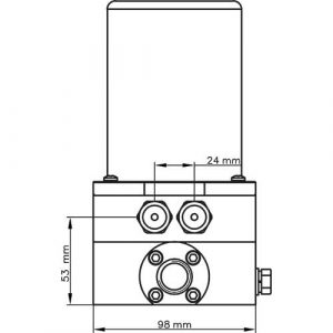
- When installing the GD 300/GD 500 under the ceiling, a distance of at least 25 cm from the lid to the ceiling must be complied, that the lid can be removed for connecting the sensor cable.
- When installing the GD 300 Ex Wafer note that the lid is on the left-hand side, a minimum distance of 25 cm is required.
- In case of falling below the Qmin (measuring range) display of measured values is not possible.
- The flow meter GD 300 Ex / GD 500 Ex can be installed in a horizontal or vertical position. A condensate drain is integrated in the measuring head, which ensures the outflow of condensate of 100% wet gas without sediments
- The inclined measuring head ensures the outflow of condensate when installed in horizontal pipes.
At low flow rates the density (or actually the viscosity) of the gas influences the accuracy.
Above the limit value (Qt), the accuracy is 1,5 % of the measured value. Below Qt the accuracy is 5 % of the measured value.
Example measurement range:
Qt bei 1,5% accuracy
Exampla:
At a density of x kg/m3 the limit value is Qt = y % of Qmax.
For natural gas with a methane component of 85 % a density of 0,85 kg/m3 is assumed.
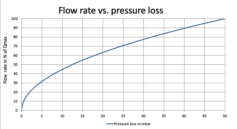
The diagram applies to gases with a density of air at NTP (0°C and 1013 mbar). The decrease of pressure is always proportional to the gas density. If e.g. the operating pressure rises by 100% the pressure drop doubles.
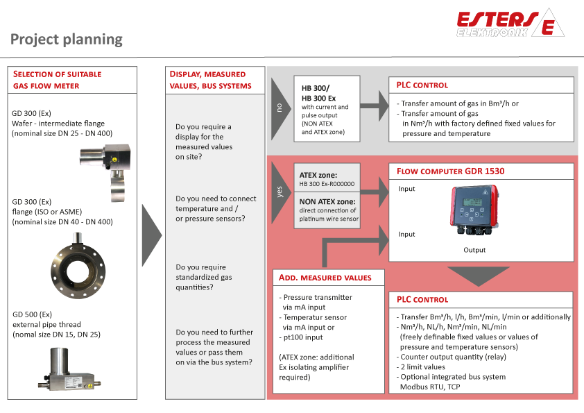
Flow Computer GDR 1530 G2

The 1-channel flow computer GDR 1530 G2 is used to calculate the current gas volume of the Fluidistor gas flow meter GD 300 (ex) / GD 500 (Ex) as well as gas flow meters with a reed relay or open collector output.
On an hourly or minutely basis, the current gas quantity can be displayed in cubic meters or liters. The total counter reading can be displayed in cubic meters or liters. The counter can have 9 digits up to 999 million cubic meters. The resolution is 0.1 liters.
You need a volume corrector to connect a gas flow meter from another supplier. You can find more information about our volume correctors at www.esters-elektronik.de!
Highlights
- Connection of GD 300 / GD 500 directly to platinum wire sensor (NON-ATEX zone), ATEX zone withHead Barrier HB 300 Ex.
- 4-line display of 20 characters
- Multilingual menu (german, english, italian, french, spanish, more in
progress) - Full device configuration via touch keypad, no additional software required
- Integrated W-LAN hotspot with full access to the device via web browser
Optional LAN interface for integration into the plant network
- Protection of the configuration via security code
- Recording of essential actions with time stamp in the system logbook (device start, sensor failure, overrange, etc.)
- Limit value Monitoring (2 limit values)
- Housing material made of UV-resistant polycarbonate,
protection class: IP 65 - Persistent meter reading for 5 years
- Integrated real-time clock, battery buffered over 5 years
- Integrated barometric sensor for recording the atmospheric pressure
- Standardization according to DIN 1343, DIN 6358, DIN ISO 2533 and DIN 102/ISO 1-1975
- Freely scalable current output for the current flow
- Adjustable pulse weighting (0.1, 1 or 10 or 100 m3 per pulse)
Optional data transfer via Modbus RTU and Modbus TCP
W-LAN hotspot with full access to the device via web browser
Download
ATTENTION!
- Devices with firmware version V 9.x, V 10.x must not be upgraded to V 12.x
- Devices with firmware version V 9.x must not be upgraded to V 10.x
- Devices with firmware version V 9.x, V 10.x, V 12.x must not be upgraded to V 13.xx
- Devices with firmware version V 10.x must not be downgraded to V 9.x
- Devices with firmware version V 13.x must not be downgraded to V 9.x, V 10.x, V 12.x


